DIY Line Conditioner, rig your own
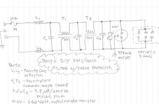
A Line conditioner will have a schematic like this one, or a variation thereof:
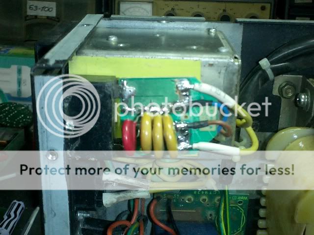
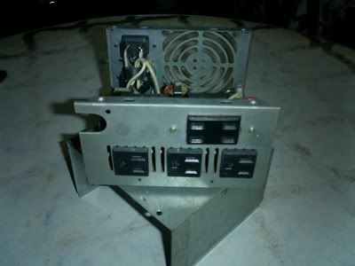
implemented, looks like this:
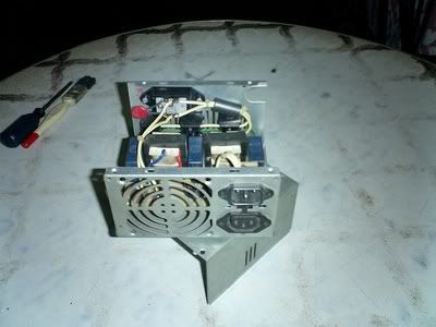
If you are using an earthing system, then two 0.01/1kv or better disk ceramic capacitor can be wired in between the "hot" sides of the line and the junction earthed, this serves as a drain path for rfi noise. Since i do not use any earthing system in my house, I opted to forgo this in order to avoid nasty shocks that could otherwise occurr with those caps installed and connected to casing. The X2 caps are 1.5uf self healing types rated for 630 volts dc. At a radio frequency of say 400khz, it will have an impedance of 0.26ohms. The series chokes will have an inductance of about 10uH each, since there are 6 in series, it will have a total inductance of about 60uH, and so at about 400khz will have an equivalent impedance of about 150ohms, so ignoring phase for a moment, and treating them as pure resistances, we see that attenuation factor will be 150/0.26 or about 580. Of course this is not by all means accurate but gives you a pretty good idea of things to come.
Line conditioners have long been employed in appliances such as tv sets and smps, atx psu's and industrial equipment, before the audiophile community got wind of it. And in the European Union it is mandatory for appliances that employed SMPS in their power supplies.
Examples:
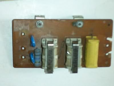
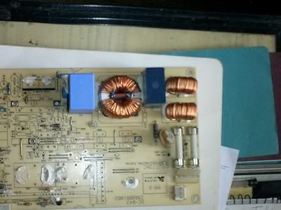
1. this came from a National Panasonic Color TV circa 1970:
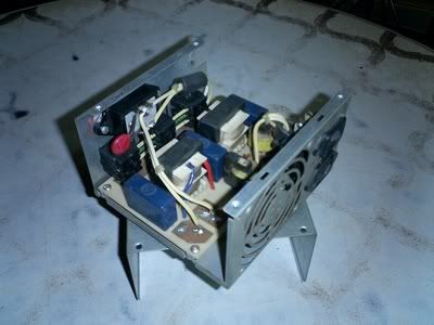
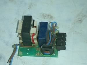
2 these came from an ATX pc psu:
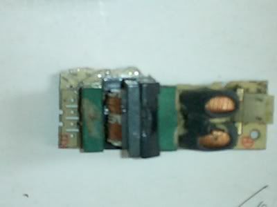
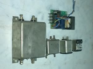
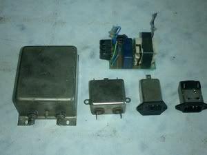
3. these devices, are emi filters that came from industrial equipment:
Here are parts you will need for constructing a line conditioner:
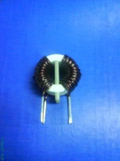
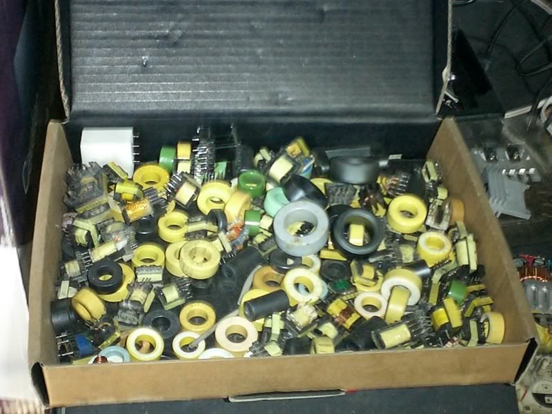
1. common mode chokes:
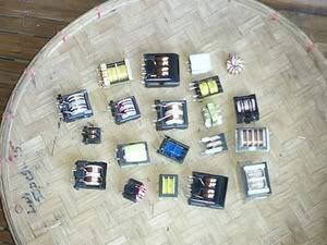
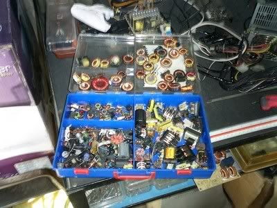
or you can use any one of these to wire one:
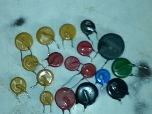
2. MOV's metal oxide variable resistors:
implemented, looks like this:
If you are using an earthing system, then two 0.01/1kv or better disk ceramic capacitor can be wired in between the "hot" sides of the line and the junction earthed, this serves as a drain path for rfi noise. Since i do not use any earthing system in my house, I opted to forgo this in order to avoid nasty shocks that could otherwise occurr with those caps installed and connected to casing. The X2 caps are 1.5uf self healing types rated for 630 volts dc. At a radio frequency of say 400khz, it will have an impedance of 0.26ohms. The series chokes will have an inductance of about 10uH each, since there are 6 in series, it will have a total inductance of about 60uH, and so at about 400khz will have an equivalent impedance of about 150ohms, so ignoring phase for a moment, and treating them as pure resistances, we see that attenuation factor will be 150/0.26 or about 580. Of course this is not by all means accurate but gives you a pretty good idea of things to come.
Line conditioners have long been employed in appliances such as tv sets and smps, atx psu's and industrial equipment, before the audiophile community got wind of it. And in the European Union it is mandatory for appliances that employed SMPS in their power supplies.
Examples:
1. this came from a National Panasonic Color TV circa 1970:
2 these came from an ATX pc psu:
3. these devices, are emi filters that came from industrial equipment:
Here are parts you will need for constructing a line conditioner:
1. common mode chokes:
or you can use any one of these to wire one:
2. MOV's metal oxide variable resistors: